(Principle)

Solar motor runs about 300-1000rpm with 15-100mA current while most popular DC toymotor does 5000-10000rpm
with 100-500mA.This slower rotation and  smaller current make rotation power weak and easily impeller stops
 rotation by powder dust.

In this circuit(Fig.1),solar motor is connected in serial to resistor R1 and current is limited about 20mA at
 constant roration.The terminal voltage is about 1V,then Q1 is activated, LED light on and Q2 is off.
So buzzer does not sound.
  Fig.1


But at the time Impeller (motor) rotation is interruped ,this falls down almost 0V. Q1 goes off and LED turns
 off, Q2 activated and buzzer will sounds.

Thus we can recoganize dust level is ready to disposal.

At the moment when starting rotation, Solar motor needs much more current.C1 gives rush current to do this.
Spredsheet1 shows parts list.
| Parts List | ||||
| Parts number | Parts Discription | E.QV. Parts in US | Parts Seller | |
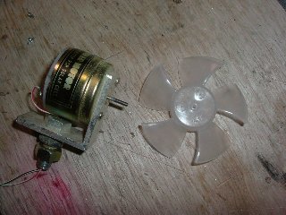
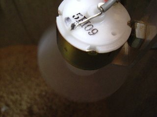
| Solar Motor | H-151Solartek | #700-60062-00 | http://store.sundancesolar.com | |
| Impeller | Plastic 60mm dia. | Note1 | ||
| Q1 | 2SC1815 | 2SC1775A | www.allelectronics.com | |
| Q2 | 2SC1815 | 2SC1775A | same above | |
| D1 | 1S1558 | IN4002 | same above | |
| LED | Unknown spec. | LED-120 | same above | |
| Buzzer | 12V DC | SBZ-100 | same above | |
| C1 | 470uF 25V | 470uF 25V | same above | |
| R1 | 600 ohm | Note2 | ||
| R2 | 10Kohm 1/4W | 10Kohm 1/4W | same above | Note3 |
| R3 | 1Kohm 1/4W | 1Kohm 1/4W | same above | Note3 |
| R4 | 10Kohm 1/4W | 10Kohm 1/4W | same above | Note3 |
| note1 | If you don't find simular one,You can make it yourself | |||
| note2 | get this value by pararell connection of multiple resistors | |||
| note3 | sold 10 pieces minimum |
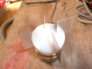
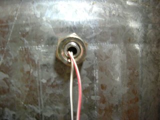
(Construction)
Make some holes on a piece of alminium angle to place solar motor and holding screw .I also made a through
 hole from top to bottom in 8mm hex bolt to lead motor cable.Then unit is placed with this 8mm bolt and nuts
on the side of dust can. Also if you like,you can place unit at the cover of dust can.
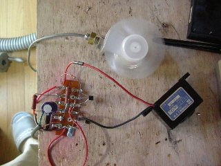
The circuit is simle, so is constructed on a lag terminal by soldering.R1 is assembly of multiple resistors.
See Fig.2. Resistors is sold 10 pieces minimum,so this may make good use.
(Testing)
After finishing construction, check all connections ,then connect 12V DC adaptor.Buzzer sounds for about
 a few seconds, motor starts and gradually rotates up,and LED turns on.
Trying to tatch impleller with your finger, if you feel little much power to stop(Impeller splashes out
powder dust),remove one 10Kohm form R1 assembly.In case  motor rotates not constantly,add one more 10Kohm
 to R1 assembly.
When rotation stops,LED turns off and Buzzer sounds.

Motor does not start again when you leave your finger, so disconnect DC adaptor once and connect again.

I keep this sensor running during I'm in my shop.

(important)
*Sorry,I made test with parts available in Japan,you may need some cut and try.
Especially,The detection sensitivity depends on the radius and the shape of impeller(propeller).

*If impeller rotates in the way to dig dust,then reverse motor connection so that impeller press dust.

*If your don't like buzzer noise, remove R4,Q2 and buzzer then you can use LED indicator only.
*To prevent impeller from striking by particle dust or something, It will
be better to surround impeller with wire guard.
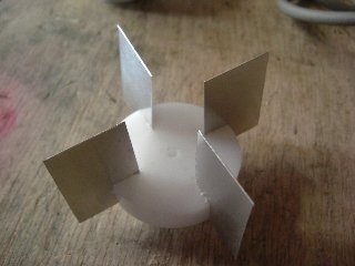
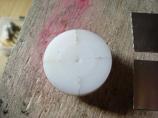
(Making a detecting impeller)
I made four small blades with alminium sheet(0.3mm thick, 20*30mm) and a small plastic rod(30mm dia. and 10mm thick).
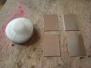
Then ,I made a 2.0mm dia. through hole at the ecxact center(= motor shaft),
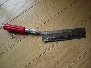
and cut four slits with XACTO saw(the blade thickness 0.27mm)
Insert blades into slits. If you feel it loose, use adhesive(for metal
and plastic).
I don't know this shape is best or not, but it stops certainly with powder
dust. You can make some modifications.